
Drone Frame Optimization
In the course MECH 465: Computer Aided Design at Queen's University, I worked with a group of students to design and optimize a drone body frame for a launch maneuver.
Collaborators: Sabrina Button, Jaime Glerum, Torin Lam, Simon Forero
The project focused on redesigning a standard drone frame made from 6061-T6 Aluminum Alloy. We utilized a bottom-up modeling strategy in ANSYS to perform Finite Element Analysis (FEA), focusing on a quarter-symmetry model to increase computational efficiency while maintaining high accuracy.
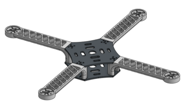
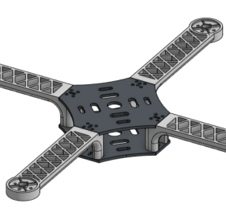
Figure 1 - CAD model of the drone frame.
Approach
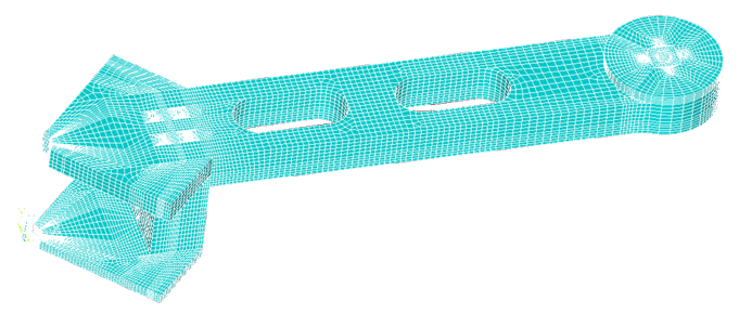
Our analysis simulated a launch maneuver by applying pressures for air drag (0.002 MPa) and motor thrust (0.005 MPa). To achieve an optimal design, the team employed a coarse mesh optimization strategy to quickly iterate through design vectors before validating the final results with a fine mesh of over 500,000 elements.
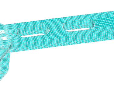
Figure 2 - Completed quarter drone frame ANSYS mesh using the bottom-up method.
Results
The final "Best Design" featured a 10% reduction in arm thickness and enlarged weight-reduction cutouts. This optimization successfully reduced the total mass of the frame from 217.64 g to 164.84 g, representing a significant 24% total mass reduction from the original starting design. Despite the reduced mass, the frame remained well within safety margins, with a maximum Von Mises stress of 0.614 MPa, far below the material's yield strength, and a tip deflection of only 15.03 mm.
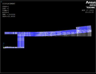
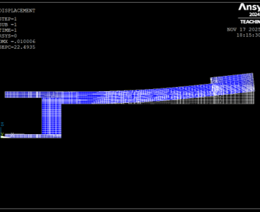
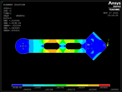
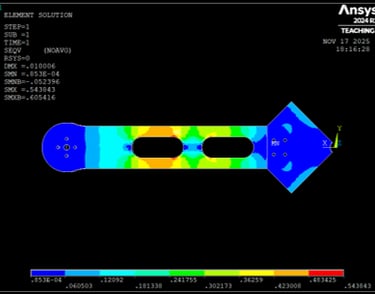
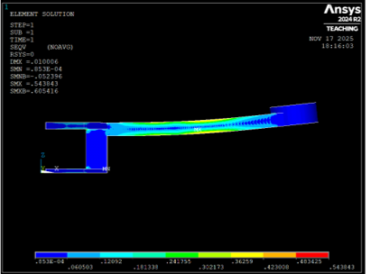
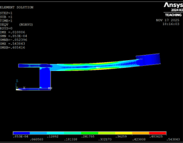
Figure 3 - Deformation plot.
Figure 4 - Stress contour (top).
Figure 4 - Stress contour (side).